
3D Design Tips for Fibre Reinforcement in Additive Manufacturing
- sabinagg
- Jul 23, 2021
- 4 min read

Updated: Jan 12, 2022
Markforged offers the unique capability to leverage continuous fibres to further strengthen and stiffen your 3D prints. It’s a useful way to use plastic components in demanding applications, replacing the need for metal or other higher strength materials.
Like all manufacturing processes, there are design considerations and limitations for fibre reinforcement using Markforged technology. In this guide, we will discuss some of these considerations and constraints, and reinforce the importance of designing for the production method and application.
Choosing Fibre
Choosing a fibre depends on the application of your part and will affect how this part behaves in its environment. It can affect part strength, stiffness, failure condition and even heat resistance. Below is a short overview of the fibres available on Markforged 3D printers, which we cover in more detail in our Selecting Fibre tutorial.
Carbon Fibre: The stiffest and strongest fibre, with the highest strength-to-weight ratio.
Highest thermal conductivity
Fibreglass: A cost-effective fibre, providing similar strength to Carbon Fibre, but with a
lower stiffness (approx. 40% lower). Electrically insulating
Kevlar: Tough and lightweight fibre, ideal for impact or abrasion resistance
High Strength High Temperature Fibreglass: Strong fibre for higher temperature environments, over 105°C, with a heat deflection point of 150°C
Any of these listed fibres can be printed using the Markforged X7 Industrial 3D Printer and the Markforged Mark Two Desktop 3D Printer. Contact the CREAT3D Team to learn about the full range.
Incorporating Fibre
There are two different ways to lay fibre using the Markforged printers, which will be determined by the part that you are printing. The two options that are available in Markforged Eiger software are ‘Concentric Fibre’ pattern and ‘Isotropic Fibre’ pattern, which is a combination of a surrounding loop of fibre and a filled cross section of fibre. The two options are shown below.

Each fibre reinforcement option can be applied to a single layer, or groups of layers, within a part. This allows for strategic placement of fibre to optimise the reinforcement according to the part’s loading conditions. As we cover later in this guide, fibre strategy is also limited by part geometry, orientation and wall thicknesses.
Laying a single path of fibre
Firstly, we will look at laying a closed loop of fibre through a plastic part. When reinforcing a thin section, you will need to use a concentric fibre ring, which will lay a single path of fibre throughout this narrow geometry.
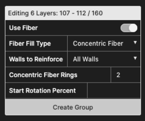
In the example below, laying fibre using the Concentric Fibre pattern, this part is a thin walled structure with a hollow core. As it is a hollow part, we can only lay the fibre concentrically around the walls – there is no internal volume to lay in isotropic fibre layers.

As you will see in the example above, we have selected 3 concentric fibre rings, however Eiger has recognised that the wall section is too thin to apply 3 rings of fibre and has automatically added the maximum number of rings that there is space for, which in this case is a single ring of fibre.
The width of a fibre path is approximately 1mm. Taking into account the shells of plastic material either side of this fibre strand, the minimum part thickness that can be reinforced is approximately 2.9mm. This is the minimum thickness you should incorporate into your design if you want to reinforce with fibre.
Isotropic v Concentric?
For some parts, you may have a combination of sections which can only be filled with single paths of fibre and sections that can be filled with full isotropic paths of fibre. The example below shows a part which on the left-hand side is a hollowed section with a wall thickness of 2.9mm and on the right-hand side, a solid volume.
We’ve selected the isotropic fibre pattern with 2 concentric rings of fibre to surround this, to place fibre throughout the entire cross section. Eiger has automatically detected the minimum wall thickness on the left-hand side hollow section and has continued the single outer loop of concentric fibre throughout these walls.

Laying fibre through projections in a part
We’ve covered the design considerations for a continuous loop of fibre, but what about thin part sections, such as gear teeth or turbine blades, which project from the main body of a part? In this case, fibre needs to double back on itself to make a concentric ring, and with this comes another design consideration.

As shown in the example, the wall thickness of the projection needs to account for two paths of fibre, looping back on itself towards the tip of this projection. Taking the additional fibre path into account, the minimum width for a projecting feature is 3.8mm, if you want to reinforce this projection with fibre.

Top Fibre Design Considerations
• The minimum width of a part with a continuous loop that can be reinforced with Markforged composite filament is 2.9 mm
• The minimum width of a fibre-reinforced projecting feature is 3.8 mm
• A combination of fibre patterns can be used in a single part
• As a general guide, use concentric for a thin walled structure with a hollow core. Use isotropic for placing fibre throughout the entire cross section
This tutorial forms part one of a series of tutorials and blogs from our Applications Engineering Team, sharing our learnings and knowledge in our free Knowledge Hub.


Comments