
Embedding Components
- sachinpatel
- Jan 30, 2020
- 6 min read
Updated: Jan 12, 2022
Combining multiple materials, components and off-the-shelf parts can help you elevate your 3D prints. One way to easily do this, is to utilise the Markforged 3D printers and their ability to accurately pause at a given height within the print process. This powerful function allows for parts to be embedded within the 3D printed component, securely capturing it in place. Often this can mean a better fit and better functioning part or assembly.
The range of components that can be embedded and combined is almost endless! Anything from RFID tags, sensors, electronic components to nuts and fasteners, and other off-the-shelf components such as reinforcing bars.
This tutorial forms part one of a series of tutorials and blogs from our Applications Engineering Team, sharing our learnings and knowledge in our free Knowledge Hub. More content will be added over the coming weeks.
Embedding a Thread - Tutorial on how to embed a thread into the printed part. Continue to read on or download via our Knowledge Hub.
Combining Metal & Composite - Short insight into benefits of combining multiple materials and AM technologies for a single part. Read Blog
Incorporating Threads
One of most desired components to embed in a 3D printed part is a thread.
There are a number of ways to incorporate a thread in your 3D printed components, with some being more effective and reliable for the given application, than others. A thread can be designed in CAD and printed, tapped into your part during post-processing, or you could use off-the-shelf threaded inserts, embedded during or after print.
The first stage is to understand which method of incorporating a thread is best suited to your particular part or application.
Printing a thread
Printing a thread or tapping a hole in a printed component are often the easiest and simplest ways to create a thread, especially for single-use applications. However, both tapped and printed threads are easy to overload and can strip out. A few things to bear in mind:
How often do I need to use this thread? If it’s more than a few uses, should I consider a more reliable and longer-term option?
What wall thickness should I use, to ensure the tapped thread doesn’t cut through to the infill of my part?
Adding a thread, post print
The other option is to add a prefabricated insert into your part after it’s finished printing. If using heat-set inserts, you’ll just need to design a tapered hole in your part, leaving enough clearance to set the insert in place, allowing plastic material to melt and reflow around the insert, making it stronger and more secure.
Embedding a thread during 3D printing
One of our preferred methods is to utilise the pause feature on the Markforged range of 3D printers. Embedding nuts into 3D printed parts increases the overall pull-out strength, compared to push fit or heat-set inserts, whilst also allowing more material to surround and capture the embedded component within the part.
Embedding a Thread Tutorial
We’ll cover off the basic design process for embedding a nut into a 3D printed bracket, using Markforged slicing software, Eiger, to set an accurate pause height at which we can embed our component during print.
Design Guidelines and Considerations
1. Tolerances
One of the most important things to consider is the tolerances of your 3D printer. We’re using the Markforged range, which are built for high tolerances and accuracy, so a gap of between 0.05mm – 0.08mm on all sides will give you a close fit when you embed your component.
2. Top surface
If the top surface of the embedded component has a flat face, you should be able to print directly over this, when the print is resumed. For some larger surface areas, you may need to add a layer of glue to the top surface, to help with adhesion of the fresh plastic being extruded from the nozzle, or create a filler piece or top cap (more on this later). The most important thing to remember is that your embedded component must not protrude from the cavity above the printed layers, as this will lead the print head to collide with the embedded component!
3. Support material
If other areas of your part require support material, you’ll need to leave support generation enabled and then remove any that will build in the insert cavities during printing. If your part is self-supporting and doesn’t require support material, it’s best to disable support generation, to avoid any unnecessary material build-up in the insert cavities.
4. Selecting nut type
Although hex nuts are more common, square nuts are generally better for embedding applications as they are less likely to strip the inside faces of the cavity. In this blog, we’ll use hex nuts, as they’re a good example of the design considerations when embedding along the Z axis.
Embedding nuts in the XY Plane
1. Designing the cavity
Once you have your bolt hole designed, create a plane for the base of the cavity, as shown below.

Measure the dimensions of the nut you are embedding and sketch out the cavity for this on the new plane. We’re using an M6 nut, which when measured across the width of the flat sides, is 9.82mm wide.
Accounting for our printer tolerances, we’ll add 0.05mm offset. Adding this offset to the measured dimensions of the nut gives us a cavity width of 9.92mm (9.82mm + 0.05mm + 0.05mm). To be on the safe side, we’ll round up to 10mm, as shown below.

We'll now create the depth of the cavity. When measured, the thickness of the M6 nut is 4.90mm. Accounting for some clearance, a 0.20mm gap is recommended as a minimum. Cut-extrude the sketch through the body by the calculated amount, which in this case is 5.10mm.

2. Adding a pause in Eiger
Using Markforged Eiger software, we can add a pause at a chosen height within the part. Within the internal view screen, scroll to the layer at which the roof the cavity begins, which in this case is layer 67.


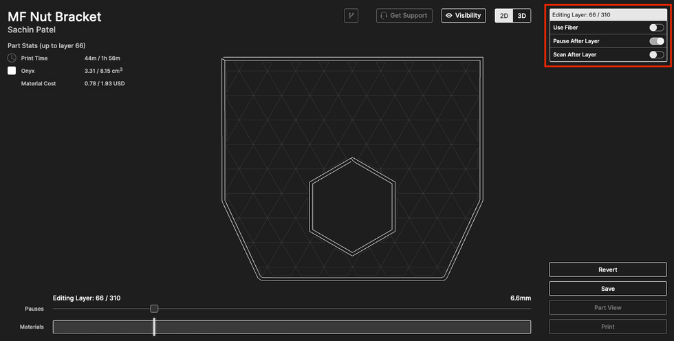
The pause needs to be added to the layer BEFORE the roof of the cavity is shown (in our case layer 66). Select "Pause After Layer" on this layer, to add to the pause.
3. Printing the part
Once the part has finished slicing, it’s ready for printing on one of the Markforged 3D printers. Eiger will send over an email once the pause occurs, notifying the operator that the printer is idle and waiting for an action.
TOP TIP: Try not to leave this pause time for longer than a few minutes. The longer the gap between resuming the print, the more likely you’ll experience poor interlayer bonding and delamination between the printed layers and the remaining layers.
Insert the component into the cavity and, as long as the part fits and sits below the printed surface, resume the print. The build plates on Markforged printers have a positioning accuracy of 10 microns, so you can remove the build plate to embed inserts, if required.

Embedding nuts in the other planes
Components can be embedded in other planes - it just takes a little more design consideration and, in most cases, a secondary component to help secure the embedded insert in place.
Going back to our simple bracket example, let’s say we now want to embed a nut in the upright section of the bracket. For this, we would need to change the shape of the cavity to allow the component to be dropped in after the pause, as well as ensure a suitable surface for the next layer of filament to adhere to.

In the example, there is clearance for the nut to slot into the cavity, but the sides of the roof are left unsupported, which isn’t good practice especially for larger inserts.

A self-supporting overhang, as shown to the left here, will eliminate this issue. However, once embedded, the nut is left free to move within the cavity, therefore not providing a secure thread.
The resolution to this is to create a secondary printed component as a ‘filler piece’, which will secure the nut in position and provide a flush surface for the next layer to adhere to. The first step is to add more space within the cavity.
Then create the small ‘filler piece’ that will sit above the nut, filling the void within the cavity, leaving some tolerance on the top and sides, as shown below. This component can be printed before or alongside the bracket, so that it’s ready to be inserted with the nut during the pause.


After our first pause on layer 66, we’ve added another pause for the second nut, as shown below. Once the printer has paused at layer 290, the second nut can be inserted, with the printed ‘filler piece’ ready to insert above the nut. The print can be resumed, capturing the second nut securely in place.

This tutorial forms part one of a series of tutorials and blogs from our Applications Engineering Team, sharing our learnings and knowledge in our free Knowledge Hub. Check out the hub for more guides and download a copy of this tutorial.


Comments